Diagram Editor
We access the diagram editor by clicking on the button  , located at the top of the sidebar. Here we can create diagrams
inserting various types of objects that appear grouped on the left side of the editor. The diagrams that we create here can be inserted later in the project document.
To add code, press the add button
, located at the top of the sidebar. Here we can create diagrams
inserting various types of objects that appear grouped on the left side of the editor. The diagrams that we create here can be inserted later in the project document.
To add code, press the add button  , or keyboard access (Ctrl + Insert).
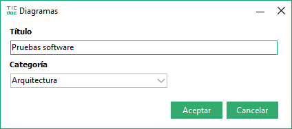
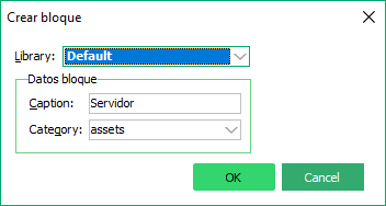
We assign a name to identify it and a category as a way of grouping diagrams with similar themes (we can use it for subsequent searches). We write the category in the editor if it does not exist, or select from the list if we have already added it.
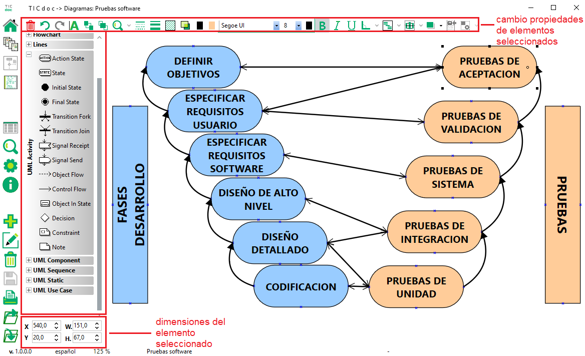
As in all editors we save by pressing the button  , or with (Ctrl + S). The diagram editor has three sections: on the left are groups of elements that we can insert, on the top
There are a series of controls that allow us to modify properties of the selected element or elements, and the rest of the screen is the editing area where we draw. Before we start inserting elements into the diagram, we can adjust properties of the
editor by pressing the settings button
, or with (Ctrl + S). The diagram editor has three sections: on the left are groups of elements that we can insert, on the top
There are a series of controls that allow us to modify properties of the selected element or elements, and the rest of the screen is the editing area where we draw. Before we start inserting elements into the diagram, we can adjust properties of the
editor by pressing the settings button  . For example, we can adjust a background grid and activate it to place the elements.
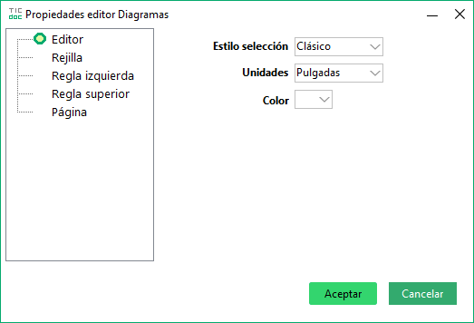
Type of selection handles, background color, and units of measure.
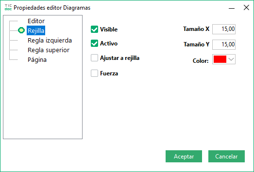
See the background grid, its color, if we adjust movements to the position and its horizontal and vertical size.
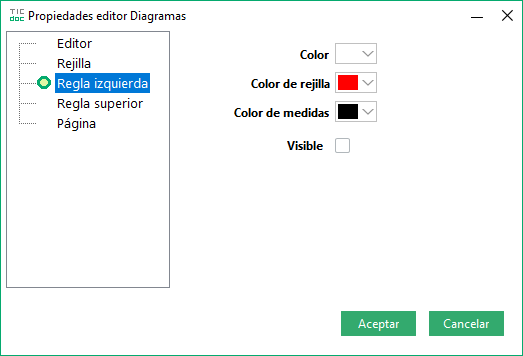
Editor Left Rule Properties.
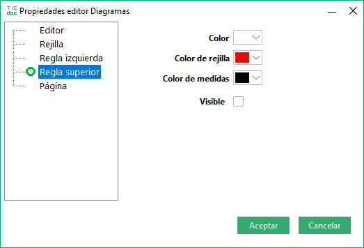
Editor Top Rule Properties.
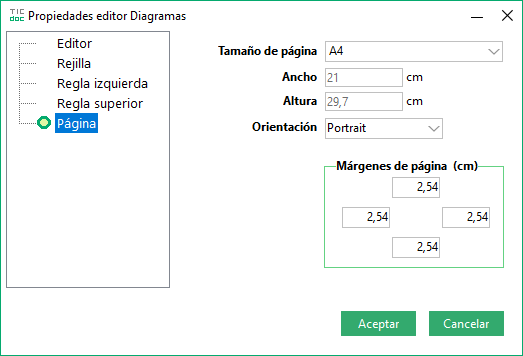
Page size and print margins
On the left side we have the elements that can be added, we select and click on the position of the editor where we want to place it. With the selected element we can move it with the mouse or with the keyboard combination (Ctrl + ↑/↓ ←/→).Using the keyboard, pressing the arrows makes it move according to the X and Y size of the grid if it is active, or pixel by pixel if it is not. The elements that we can insert in the editor are:
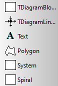
Basic.
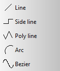
Lines.
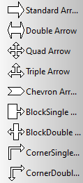
Arrows.
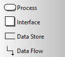
Data flow.
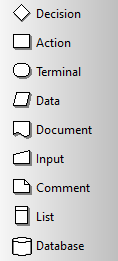
Flow chart
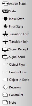
Uml activity
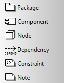
Uml component
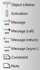
Uml sequence
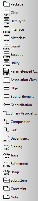
Uml static
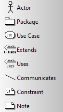
Uml use cases

When we select one or several elements we can change some of its properties by clicking on the buttons on the top bar. These actions are:
 |
Deletes the selected items. It can also be executed with Alt + Del |
 |
Edit the text of selected elements. It can also be activated with F2 |
 |
Position selected element behind the others |
 |
Position selected item above others |
 |
Zoom applied in the editor |
 |
Style of the selected line |
 |
Thickness of the selected line |
 |
Element fill color transparency level |
 |
Element border and background color |
 |
Text font, size and color. |
 |
Bold, italic, and underline style of element text. |
 |
Angle of the selected element. |
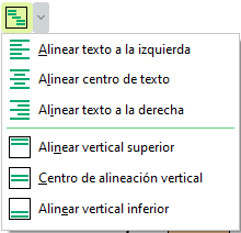 |
Text alignment (horizontal and vertical positions). |
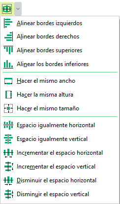 |
Position and dimensions of the selected elements. Some of the options need to have two or more items selected and in other cases three or more. |
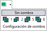 |
Shading type (size, spacing, and color). |
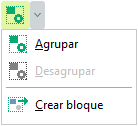  |
With two or more elements selected we can group them to select it and move it as a single object. We can also create a block with those elements, assign it a title and add it to the elements library to insert it other times in the editor. We can ungroup a series of grouped elements with the ungroup option in this menu. |
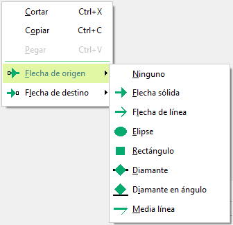 |
If we click with the right mouse button on a line, options appear in the contextual menu to change the line endings (origin or destination), with different shapes. |
To print the diagram, click the print button  , located at the bottom of the sidebar. We see a preview of the
same according to the dimensions of the page that we have assigned in the settings . The diagram can be exported by pressing the button
, located at the bottom of the sidebar. We see a preview of the
same according to the dimensions of the page that we have assigned in the settings . The diagram can be exported by pressing the button
 , where we find two options: export as image (en formatos png, bmp o wmf), or export with the extension dgr, what is the native extension
of the diagram. Diagrams that we have exported in that format (*.dgr) we can add them to the editor by pressing the button
, where we find two options: export as image (en formatos png, bmp o wmf), or export with the extension dgr, what is the native extension
of the diagram. Diagrams that we have exported in that format (*.dgr) we can add them to the editor by pressing the button  . Must take into account
In this case, the content that we may have in the editor will be replaced by that of the one in the file.
. Must take into account
In this case, the content that we may have in the editor will be replaced by that of the one in the file.